Wiring Instructions
To wire the F-5500, unscrew and remove the enclosure cap and loosen the two captive screws on the display assembly. Rotate it open to access the wiring terminals.
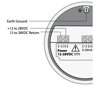
Device Input Power
Power Input Requirements: 12-28VDC Supply. At 12VDC – 500mA. 24VDC-250mA.
4-20mA Output Wiring: Customer Supplied Power Source

Pulse Alarm Output Wiring: Customer Supplied Power Source
*In order to use the Pulse/Alarm feature on the Model F-5500, this feature must be chosen when the meter is ordered from the factory. Pulse output not available with meters ordered with RS485 Modbus RTU and BACnet MS/TP.

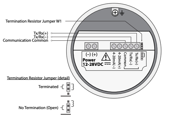
RS485 Wiring for Modbus RTU
*Connect a 120 ohm termination resistor on the F-5500, if this is the last device on the modbus chain, set jumper W1 to TERM position.
*Modbus RTU feature must be chosen when it is ordered from the factory.